
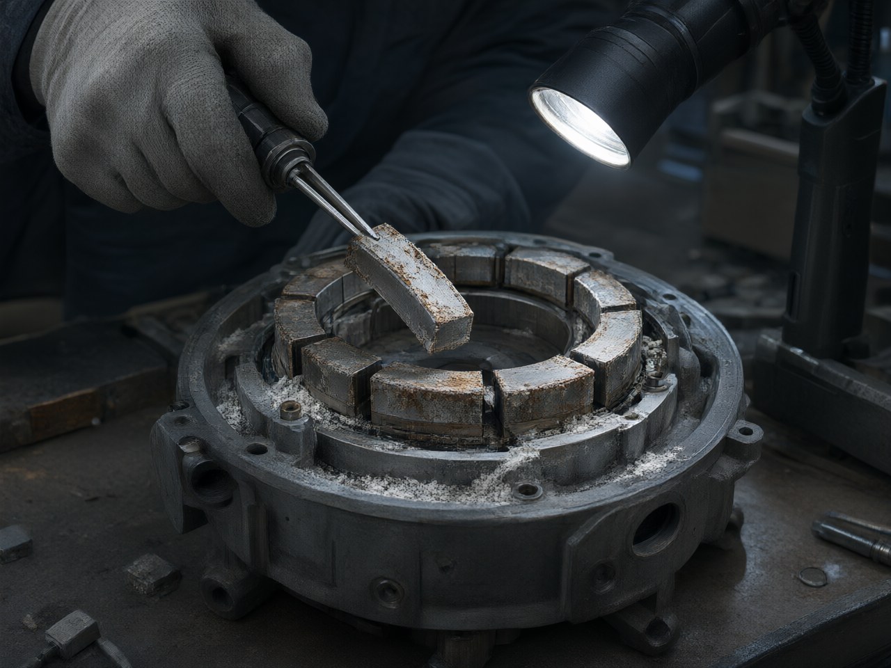
In permanent magnet assemblies, the corrosion resistance of sintered NdFeB magnets directly dictates maintenance intervals and warranty risks. When moisture penetrates poorly coated magnets, it causes internal oxidation, leading to magnetic field degradation, torque loss, and…
How Does the Corrosion Resistance of Magnetic Materials Affect Equipment Maintenance Costs and Reliability?
Corrosion resistance of a magnet is a maintenance-line item and a warranty exposure. In many permanent-magnet assemblies the magnet is the least accessible component to replace, so the coating system often sets the service interval of the magnetic assembly. An unprotected sintered NdFeB magnet can lose magnetic material in humid, saline or condensate-exposed service, and the field drop appears as falling torque, rising current draw, slower response, or a sensor drifting out of tolerance. The cost that follows is the disassembly labour, the recalibration, the production downtime and, in regulated products, the re-qualification of a changed part.
Where the design decision actually sits
Design engineers usually meet this question as a coating call made late in the project, once the magnetic circuit is frozen. Coating thickness and chemistry buy corrosion life, but they also consume radial space, add a plating tolerance band, and change the effective air gap. A thin electroplated nickel-copper-nickel stack is common practice for sintered NdFeB; thicker epoxy, or multi-layer zinc or nickel systems, can extend salt-spray life at the cost of dimensional stack-up and uneven edge coverage on sharp corners. Procurement meets the same question as a specification line: which corrosion test, which duration, which acceptance criterion, and who carries the cost if the lot fails in service.
Corrosion performance of magnetic assemblies is specified by reference to recognised test methods rather than by an absolute lifetime figure: neutral salt spray per ASTM B117 or ISO 9227, damp heat per IEC 60068-2-78, and, for automotive or outdoor equipment, cyclic salt mist per IEC 60068-2-52 or the OEM standard. These are accelerated methods. Correlation with field life depends on the environment, the assembly sealing, and coating edge quality.
Comparing protection routes against the decision criteria
The comparison that matters is which protection route fits the assembly geometry, environment class and service-access model.
| Protection route | Typical corrosion performance | Effect on assembly | Best fit | Main limitation |
|---|---|---|---|---|
| Electroplated Ni-Cu-Ni | Thin metallic barrier; handling durability is good; salt-spray life depends on porosity and edges | Dimensionally predictable; adds a plating tolerance. The copper interlayer is non-magnetic and adds to the effective gap | Indoor drives, motors in sealed housings, encoder magnets | Edge and barrel coverage depend on racking; poor pre-treatment leads to blistering |
| Epoxy or phenolic coating | Thick organic barrier; protection depends on a continuous, fully cured film | Consumes space; harder to hold tight tolerances | Outdoor pumps, magnetic couplings, wet or condensate environments | Thickness uniformity and cure quality dominate the outcome |
| Zinc / zinc-alloy systems | Used for mild environments at low cost | Small dimensional impact | Cost-sensitive indoor assemblies | Shorter life in chloride or acidic atmospheres; a breach exposes the active magnet surface |
| Stainless or polymer encapsulation | High environmental resistance when the barrier is continuous | Large volume penalty and a changed gap. A conductive can dissipates eddy-current loss as heat | Washdown, chemical exposure, and duties that need a continuous barrier | Lower flux in a fixed envelope; conductive cans add thermal load on the magnet |
| Restricted-substance coating stacks | Depends on the substitute layer; qualification required | A process change may require requalification | Specs that exclude cadmium plating or hexavalent-chromium passivation | Performance varies by supplier; verify on production geometry |
Corrosion usually starts at edges, machining marks, handling damage and magnet-to-housing interfaces, not on the flat face used for coupon qualification. Encapsulating the magnet to stop corrosion also changes the magnetic air gap. In a magnetic coupling or an isolation-can drive, the wall added to keep moisture out sits in the flux path.
What corrosion costs once it starts
Moisture reaches the neodymium-rich grain-boundary phase, the most chemically active part of sintered NdFeB. Oxidation there expands the volume and lifts the coating from the inside. Once the barrier is breached, corrosion follows the grain boundaries, magnetic material is lost, and loose corrosion product can migrate into bearings, sensors or an air gap. A magnet that has lost part of its section delivers less flux, so the device keeps running at reduced output. The fault is often found late, after warranty or on a field return.
The bill is rarely the magnet price. It is the labour to strip and rebuild, the risk of damaging adjacent parts, the recalibration of an encoder or sensor set to the original field, and the documentation of a field change. On products with safety or regulatory functions, a coating change can require re-testing against the standards used for certification.
Design windows and the margin that actually protects you
For many industrial assemblies, an electroplated stack on sintered NdFeB suits sealed, temperature-controlled enclosures. Epoxy or encapsulation is the usual step once the environment includes washdown, salt fog, condensing humidity or repeated cycling through the dew point. Where a salt-spray duration is specified, define it as a qualification criterion with a stated coupon geometry and failure mode, and keep a margin between that result and the field environment.
Thermal margin and corrosion margin interact. A magnet bonded into a housing with a mismatched expansion coefficient can crack the coating interface under thermal cycling, and those cracks are where corrosion starts. Running the magnet near its maximum operating temperature also pushes the coating toward the limit of adhesion and flexibility. State the service thermal profile with the environmental class, and specify the coating against both.
On magnetic couplings and magnetically coupled drives, the isolation can material, thickness and conductivity set eddy-current heating. That heat raises magnet temperature and can shorten coating life while the outside of the assembly still looks intact. Treat corrosion and thermal management as one problem, or a design can pass salt spray on a bare coupon and fail in a hot, wet housing.
Failure modes and where this approach does not apply
The routes above are for sintered NdFeB, where moisture attacks the neodymium-rich grain boundary. Samarium-cobalt and hard ferrite follow different environmental limits; bonded NdFeB is limited by the binder as well as the powder.
A corrosion specification does not rescue a design that is wrong for another reason. If the magnet runs hotter than the load line allows, the operating point moves down the demagnetisation curve and output falls even with an intact coating. If the air gap is so tight that plating or coating build-up is a measurable fraction of it, the build-up consumes clearance, stacks tolerances and can cause interference. If the field failure is mechanical — vibration, impact or fretting — a thicker, brittle coating can make it worse.
A neutral salt-spray result is a comparative qualification. It does not model condensation cycling, galvanic coupling to an adjacent metal, or the assembly's own sealing. Where the assembly is encapsulated or potted, the coating is a secondary barrier and the specification should move to the encapsulant and the interface.
Specifying for delivery, not just for the datasheet
A corrosion specification holds only if delivered parts match it. Agree the test method, coupon geometry, acceptance criterion and sampling plan with the magnet supplier, and ask for evidence per lot rather than per family. Check coating thickness, adhesion and edge coverage on production geometry: a sharp-cornered or thin-wall magnet is a different coating problem from a disc.
AIC Engineering designs the magnetic circuit and the protection system together, so coating thickness, gap and tolerance are set in one place; supplies permanent-magnet transmission assemblies in which the isolation barrier, eddy-current loss and magnet environment are evaluated as one system; and inspects permanent-magnet product quality against the specification the customer's qualification programme accepts. Prototype builds follow the same route, so a result obtained on samples is a result production parts can be held to.
Next steps
- Write the service environment into the requirement: humidity range, salt or chloride exposure, washdown, condensing cycles, and the thermal profile at the magnet.
- Choose the protection route against assembly geometry and the tolerance budget, and specify the test method with coupon geometry and acceptance criterion.
- Verify edge coverage, adhesion and plating-induced tolerance on production parts, and hold a margin between the qualification result and the field condition.
- Contact AIC Engineering at https://www.aicmagnetics.com for a free consultation and a customised magnetic circuit and protection design. The AIC Engineering team can review the environment specification, propose the coating and assembly route, and support prototype builds with the inspection evidence the qualification programme needs.
References
- ASTM B117 — Standard Practice for Operating Salt Spray (Fog) Apparatus, ASTM International.
- ISO 9227 — Corrosion tests in artificial atmospheres — Salt spray tests, International Organization for Standardization.
- IEC 60068-2-78 — Environmental testing – Part 2-78: Tests – Test Cab: Damp heat, steady state, International Electrotechnical Commission.
- IEC 60068-2-52 — Environmental testing – Part 2-52: Tests – Test Kb: Salt mist, cyclic (sodium chloride solution), International Electrotechnical Commission.
- Directive 2011/65/EU (RoHS) and its amendments — restrictions on the use of certain hazardous substances in electrical and electronic equipment, European Union.
- S. Sugimoto, "Current status and recent topics of rare-earth permanent magnets," Journal of Physics D: Applied Physics, vol. 44,
- W. F. Brown Jr., Magnetostatic Principles in Ferromagnetism, North-Holland, 1962 — introductory treatment of demagnetisation and operating-point behaviour.