
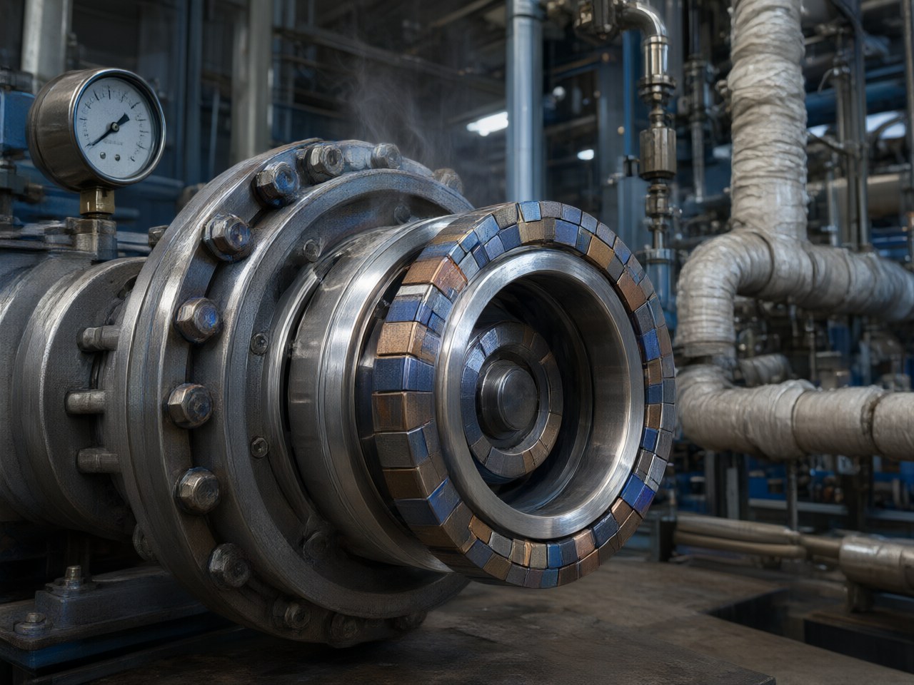
Ensuring zero-leakage sealing in magnetic couplings under high-pressure and high-temperature conditions requires balancing containment shell thickness, magnetic torque, and thermal management. The primary engineering challenge is that high pressure demands a thicker isolation…
How Is the Sealing Reliability of Magnetic Couplings Ensured Under High-Pressure, High-Temperature Conditions?
Sealing at high pressure and temperature depends on three conditions holding together. The containment shell must meet the required pressure-vessel thickness at the hot design temperature. The magnets must still deliver breakaway torque at that temperature. Eddy-current heat in the shell must not drive the shell, the magnets or the gap fluid past their limits. Two magnet rings transmit torque through a non-magnetic isolation sleeve. That arrangement turns the dynamic shaft seal into a static seal and gives zero-leakage transmission (AIC Engineering). Reliability of the seal sits mainly with the shell. The magnetic design affects it through the gap the shell forces and the heat the shell produces.
The Containment Shell Is the Seal
In a coaxial sealed coupling the inner rotor runs in the process fluid, the outer rotor runs in air, and a can separates them. Process pressure acts inside the can, so the can is a closed cylindrical pressure vessel. For a thin wall the governing stress is hoop stress:
where is internal pressure, the mean radius and the wall thickness. ASME BPVC Section VIII, Division 1, UG-27, gives the design thickness from the inside radius :
is design pressure, the allowable stress at design temperature and the joint efficiency. UG-27 applies while , equivalent to . Beyond that limit, use a thick-wall method. High pressure is the duty most likely to cross that limit.
* is taken at design temperature and falls as temperature rises, more steeply for polymers than for stainless steel or nickel alloys. * Thickness grows with pressure and radius. Inside the UG-27 range, doubling pressure nearly doubles the wall, and each added millimetre of wall is a millimetre of magnetic gap.
Coupling torque falls steeply as the gap opens. A higher pressure class therefore needs more magnet volume, or a revised pole layout, to hold breakaway torque.
Choosing a Containment Shell Material for High-Pressure, High-Temperature Service
The standard range uses 316L stainless steel, PEEK or Hastelloy C isolation sleeves. Sleeve options, media and typical fits follow the product specifications. Pressure and hot-strength rankings are general material behaviour. The catalogue states no shell pressure class.
| Containment shell | Pressure capability for a given wall | Eddy-current loss | Hot-service behaviour | Media suitability | Typical fit |
|---|---|---|---|---|---|
| 316L stainless steel | High; metal strength allows a thin wall | Present; electrically conductive | Strength holds across the −20 to +150 °C window | General chemical and laboratory fluids | Standard coaxial sealed pumps |
| Hastelloy C | High; metal strength allows a thin wall | Present; electrically conductive | Strength holds at elevated temperature | Acids, solvents, aggressive chemicals | Harsh chemical duty |
| PEEK | Lower; allowable stress calls for more thickness | Negligible; non-metallic sleeve removes high-speed eddy loss | Check strength and creep at the operating temperature | Broad chemical resistance; confirm for the fluid | High-speed pumps and energy-efficient drives |
Material options and service notes: AIC Engineering, https://www.aicmagnetics.com.
For combined high pressure and high temperature, start with a metallic shell and manage the heat it generates.
Eddy-Current Heat Undermines a Metallic Shell
The rotating field induces eddy currents in a metallic shell (Faraday induction). For a thin shell, neglecting skin effect, loss scales as:
is conductivity, the mechanical angular velocity, the gap flux density, the active length and the mean radius. With the gap flux density amplitude held fixed, do not multiply by again; pole-pair count enters only through flux density and harmonic content.
Loss climbs on the duties this article treats. Higher pressure increases , and higher speed increases . Heat is generated in the wall, so shell temperature rises and allowable stress falls. The same heat warms fluid in the gap. Near boiling, local vapour can remove cooling and lubrication, and rotor contact can breach the shell.
Practical responses:
- Limit speed or radius where the duty allows. 2. Use a non-metallic sleeve where the pressure class allows. 3. Provide a defined flush through the gap. 4. Monitor shell temperature on critical pumps.
- Confirm shell thickness to the design code at maximum temperature, with corrosion allowance and hydrotest pressure, and confirm the thin-wall formula still applies. 2. Recalculate breakaway torque at the as-built gap, including shell, clearances and tolerances, at maximum temperature. Compare it with motor peak and starting torque. 3. Check the magnet load line against the knee at maximum temperature. Use SmCo above 150 °C. 4. Estimate eddy loss from alloy conductivity, mechanical speed, wall thickness and actual gap flux density. Do not include pole-pair count through the square of electrical angular frequency. Confirm flush flow and the margin to vapour in the gap. 5. Review solids, including ferromagnetic particles, and the lubrication regime. Specify filtration or a magnetic trap where the fluid requires it. 6. Balance high-speed motor rotors to ISO 1940 G2.5 or G6.3, as specified for high-speed motor rotors. Runout consumes clearance to the shell.
How AIC Engineering Delivers Within This Window
The magnetic-circuit and structural design team sizes shell and magnets together, iterating gap, pole count and grade against the client's pressure and temperature so the two margins close on the same duty. Builds include:
coaxial sealed couplings high-temperature SmCo couplings PEEK or Hastelloy C sleeves linear couplers * custom flange and shaft interfaces for OEM pumps and agitators
Standard couplings in this range are IP68 sealed containment, with no dynamic seal. Lead time is 3–6 weeks, depending on sleeve material and torque class. Magnet quality inspection checks performance before assembly.
Next Steps
- Compile design pressure, maximum fluid temperature, speed, peak torque and fluid composition, including solids.
- Estimate breakaway torque at the gap implied by the pressure class.
- Choose a metallic or PEEK shell from the pressure and eddy-loss trade-off above.
- Visit https://www.aicmagnetics.com and contact the AIC Engineering team for a free consultation on custom magnetic-circuit design and rapid prototyping, and for a zero-leakage coupling matched to the pressure and temperature envelope.
References
- ASME Boiler and Pressure Vessel Code, Section VIII, Division 1, UG-27, Thickness of Shells Under Internal Pressure. American Society of Mechanical Engineers.
- ISO 21940-11:2016, Mechanical vibration — Rotor balancing — Part 11: Procedures and tolerances for rotors with rigid behaviour. International Organization for Standardization. Supersedes ISO 1940-1, the source of balance grades G2.5 and G6.3.
- AIC Engineering. Product specifications and application pages. https://www.aicmagnetics.com