
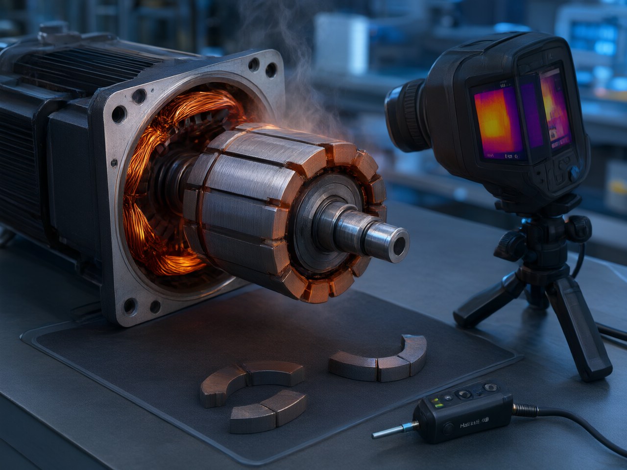
Servo motors operating at three times their peak torque face a critical engineering challenge: massive reverse magnetic fields combined with extreme rotor heat. This combination drastically reduces the intrinsic coercivity of neodymium magnets, risking irreversible…
How Should Magnet Coercivity Be Chosen for a Servo Motor at 3× Overload?
Choose the coercivity so that the magnet's knee field at its hottest operating temperature is higher than the worst local reverse field it sees at 3× peak current. That reverse field includes any negative d-axis current used for flux weakening. Keep a margin of roughly 20%, and get both numbers from your own design: the knee field from the supplier's hot demagnetization curves, and the reverse field from FEA. For sintered NdFeB rotors that run hot during repeated overload cycles, this usually points to the SH or UH coercivity class. A thicker magnet can often bring the requirement down by one class. Once rotor temperature approaches the upper limit of NdFeB, SmCo becomes the practical choice. The room-temperature Hcj on a datasheet is only where the calculation starts. A grade that looks comfortable at 20 °C can retain only about 40–50% of its coercivity by the time the rotor reaches 120 °C.
The rest of this article works through an illustrative case. It shows how the coercivity decision is made, which levers compete with buying a higher grade, and where each option fails.
The Servo Overload Decision: Grade, Thickness, or Current Limit
A servo motor rated for 3× peak torque puts its magnets under a load that the continuous rating never shows. Armature-reaction MMF scales with phase current, so 3× current drives about three times the rated reverse magnetomotive force (MMF) across part of each magnet. Under heavy saturation, 3× torque can require more than 3× current, and the check should use that commanded current. The stress is concentrated at the trailing pole edge, the magnet corners, and any region where flux-weakening current adds directly to the opposing field.
Overload is also hot. Servo duty cycles with frequent acceleration peaks raise rotor temperature through copper loss conducted across the air gap and through eddy current loss in the magnets themselves. Coercivity is lowest on that hot rotor, when later current peaks apply the reverse field. Design engineers are therefore choosing between three ways to keep the magnet operating above its knee, and procurement is choosing how much to pay for each:
- A higher intrinsic coercivity (Hcj) grade. 2. More magnet thickness, which raises the permeance coefficient. 3. Limits on current or temperature in the drive.
- UH at 4 mm, using the extra headroom for currents above the 3× case. Fault currents still need their own FEA check. 2. SH at 4 mm with a firmware Id limit, accepting the added rotor inertia in either case.
Procurement then compares the price difference between the two coercivity classes against the extra magnet mass. That comparison is usually more informative than comparing grade prices alone.
Recommended Coercivity Window and Safety Margins
The process below turns the model into a design window most servo programmes can apply.
1. Define the magnet temperature first. - Use the rotor magnet temperature during the hottest realistic duty cycle. - A 3× peak lasting a few hundred milliseconds barely heats the magnet. Repeated peaks over minutes do. - Add margin above that temperature. AIC's online magnet selection wizard applies a recommended 10 °C margin. It flags N52, N48 and N42 as acceptable only when the working temperature is confirmed at no more than 80 °C, and in that case the margin is zero. Its rule-based shortlist for sintered NdFeB includes 42M and 35M.
2. Size against the worst current, including faults. - Include peak q-axis current, maximum negative Id from flux weakening, and the terminal short-circuit transient if the drive can produce one. - Short-circuit or inverter-fault currents can exceed 3× rated. Check them separately in FEA.
3. Target a working margin on the knee. - A common engineering practice is to keep the worst local |H| at or below about 80% of . - Treat this as a design-review convention, not a published standard. Tighten it if your supplier's hot curve squareness varies between batches.
4. Use thickness before jumping two grades. - In compact servos, one step of coercivity class plus a modest thickness increase usually costs less than two class steps. - Higher classes also tend to lower Br, which reduces Kt. - Check the thin side of the thickness tolerance. The same current produces a higher reverse field in a shorter magnet.
5. Move to SmCo above the NdFeB comfort zone. - SmCo becomes the realistic option when rotor temperature, after margin, approaches the top of the NdFeB range. - It is also the right choice when temperature stability of Kt matters more than torque density. AIC's material guidance treats NdFeB as the minimum-volume choice up to 180 °C, and SmCo as the choice for high-temperature or low-drift duty.
Where the Coercivity Window Stops Working
Some failure modes cannot be fixed by raising Hcj.
Thin magnets and low permeance. With very thin arc magnets or large magnetic gaps, the open-circuit working point already sits low on the curve. Even EH or SmCo grades leave little margin at overload. The geometry has to change.
Overheating from magnet eddy currents. High-speed servos with high PWM ripple, slotting harmonics, or a conductive retaining sleeve can heat solid NdFeB magnets faster than conduction from the stator does. Coercivity then falls from heating inside the rotor. Axial or circumferential segmentation is the corrective action here. A higher grade only treats the symptom.
Kt penalty loops. A grade with heavily reduced Br can push the required current up by enough to raise the armature field. Most of the coercivity gain is then cancelled. Re-run the torque constant check after every grade change.
Assembly-stage exposure. Magnets can be partially demagnetized before the motor ever runs, through magnetization fixtures, stray fields during rotor insertion, or hot curing of adhesives. Include these steps in the temperature-field review.
Unvalidated curves. Room-temperature datasheet values say nothing about knee squareness at 120–150 °C. Without supplier hot curves, or a measured hot demagnetization test, the margin calculation above is not trustworthy.
How AIC Engineering Delivers Overload-Rated Servo Rotors
The AIC Engineering team handles servo rotor magnets as a magnetic-circuit problem from the first review. Every project follows the same flow: magnetic circuit design, material selection, sample validation and volume production.
Magnetic circuit review - The team uses the customer's overload current, flux-weakening strategy and duty cycle to check the worst-case local working point. - Grade and thickness are then balanced against Kt and rotor inertia. - Confirmed torque, dimensions and pole geometry are returned with the quotation after this review.
Rotor configuration range
Rotor assemblies are built to order. There is no fixed catalogue grade. The configurable range covers:
| Parameter | Range |
|---|---|
| Magnet material | NdFeB N42–N52, or SmCo |
| Pole count | 2–24 poles |
| Magnetization | Radial, parallel or Halbach |
| Skew angle | 0–30° |
| Rotor outer diameter | 10–300 mm |
| Working temperature | −40 to 180 °C |
| Balance grade | ISO 1940 G2.5 or G6.3 |
Prototyping and inspection - Rapid prototyping in 3–7 days lets a customer put a shortlisted grade and thickness on hardware before volume commitment. - Permanent-magnet quality inspection is part of the supply scope.
Engineers can start with the online magnet selection wizard, then send the shortlisted grade and temperature to AIC Engineering for a no-cost check of the working point.
Next Steps for Your Servo Magnet Coercivity Decision
- Gather the four inputs. Extract worst-case peak current (including negative Id and fault transients), the hottest rotor magnet temperature over the real duty cycle, magnet thickness, and effective air gap.
- Run a demagnetization FEA. Model the overload current at maximum magnet temperature, and record the peak local reverse field at the pole edges and corners.
- Compare against hot curves. Request hot demagnetization curves for at least two coercivity classes and one thicker-magnet variant. Then compare cost per rotor, Kt and inertia side by side.
- Contact AIC Engineering. Request a custom magnetic circuit design review and rapid prototyping of the shortlisted rotor options. Visit https://www.aicmagnetics.com and use Get a Quote or Contact Us. AIC Engineering will check the overload working point and quote a rotor for the torque, temperature and cost targets.
References
- Hendershot, J. R., & Miller, T. J. E. Design of Brushless Permanent-Magnet Machines. Motor Design Books,
- Gieras, J. F. Permanent Magnet Motor Technology: Design and Applications, 3rd ed. CRC Press,
- Campbell, P. Permanent Magnet Materials and Their Application. Cambridge University Press,
- Coey, J. M. D. Magnetism and Magnetic Materials. Cambridge University Press,
- Sagawa, M., Fujimura, S., Togawa, N., Yamamoto, H., & Matsuura, Y. "New material for permanent magnets on a base of Nd and Fe." Journal of Applied Physics, 55(6), 2083–2087,
- IEC 60404-8-1. Magnetic materials – Part 8-1: Specifications for individual materials – Magnetically hard materials. International Electrotechnical Commission.
- IEC 60404-5. Magnetic materials – Part 5: Permanent magnet (magnetically hard) materials – Methods of measurement of magnetic properties. International Electrotechnical Commission.
- ISO 21940-11. Mechanical vibration – Rotor balancing – Part 11: Procedures and tolerances for rotors with rigid behaviour (successor to ISO 1940-1). International Organization for Standardization.
- AIC Engineering Ltd. Application solutions, selection tools and magnet selection wizard. https://www.aicmagnetics.com